
Post by TheEnd on Nov 16, 2010 19:39:13 GMT -5
KJW M9 GBB Disassembly Guide
This is version 1.0. Any errors or problems will be fixed in future updates. If you see any problems point them out for me and it will make for a better guide.
This guide may not be copied and posted on other sites. If you wish to share the information please post a link to this thread.
Welcome to the complete KJW M9 GBB dissasembly Guide. Before you begin taking your KJW M9 apart please read the entire guide. There are springs in certain areas that can fly out when a part is removed. To help avoid this and any other confusion please read the whole guide before trying dissasemble anything.
I made this guide to help others fix their KJW M9 GBB pistols. By following this guide you are dissasembling your M9 at your own risk. If you have trouble shoot me a PM and I will be glad to help. But I will not pay for any replacement parts or pieces.
With all that out of the way, lets begin.
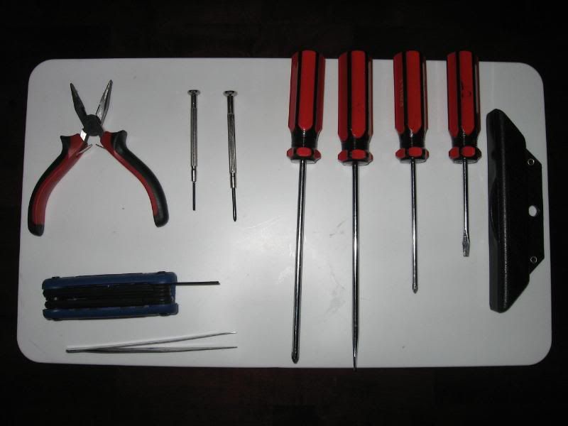
Tools needed for complete dissasembly:
- 1 set small needle nose pliers
- 1 pair of tweezers
- 1.5mm allen key
- 1 tiny flathead
- 1 small flathead
- 1 large flathead
- 1 tiny philips head
- 1 small philips
- 1 large philiphs head
If you are cleaning or lubing you will also need grease. What kind you use is up to you, but I use white lithium.
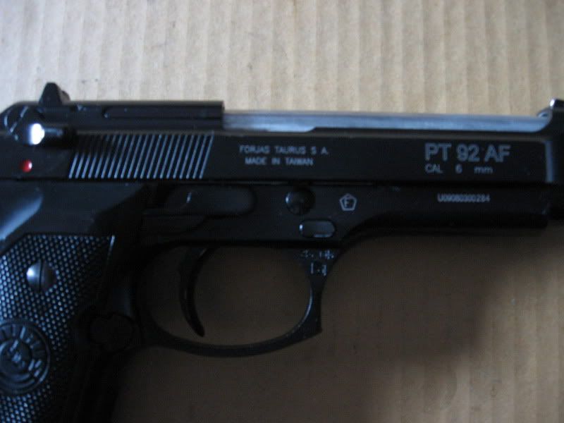
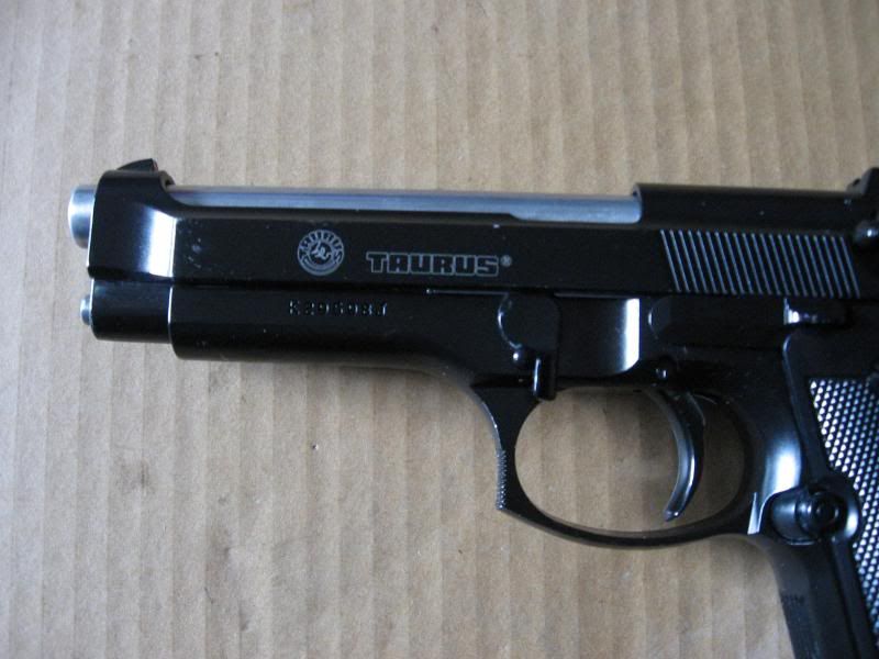
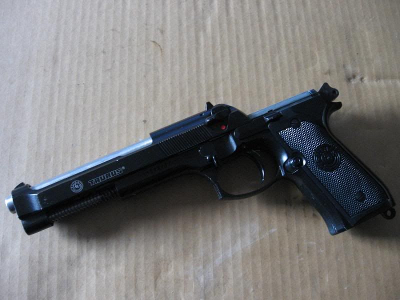
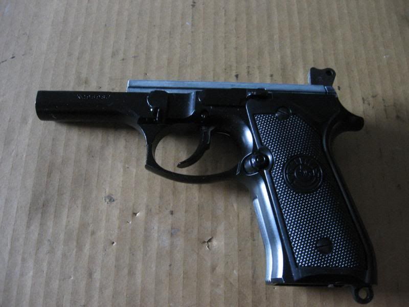
Now that you have the tools, you will need the KJW M9 GBB. My specific example is a KJW Taurus branded M9.
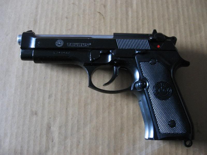
Basic teardown[/b][/color]
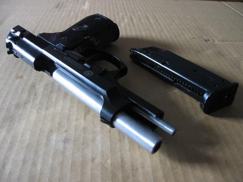
Step 1: Clear the gun. Make sure there are no BB's in the chamber and that the magazine is removed.
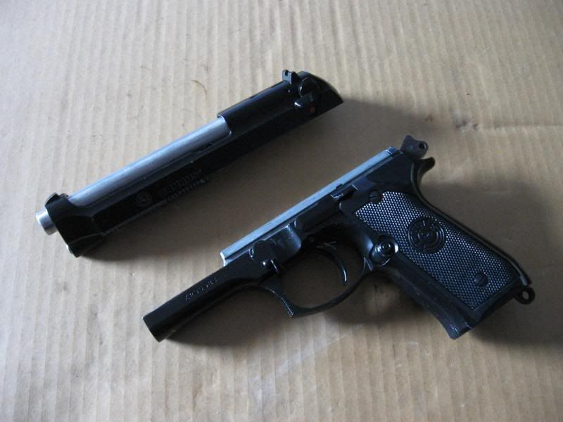
Step 2: Remove the slide.
A. Cock the hammer back.
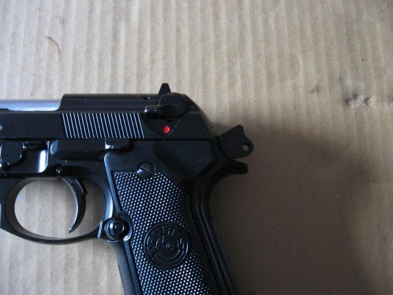
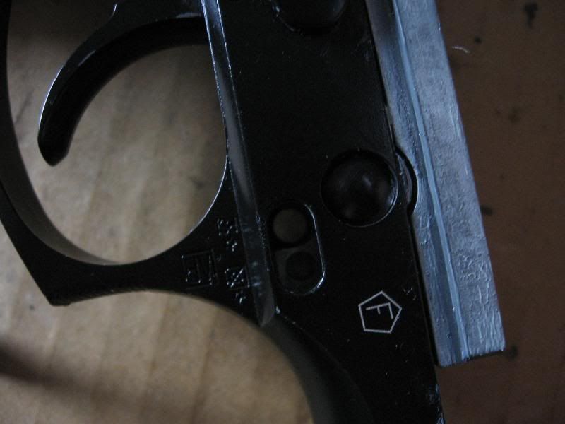
B. Press the small oval button on the right side of the frame near the trigger guard.
C. Pull down on the dissasembly lever.
D. Push the slide forward and remove it from the frame.
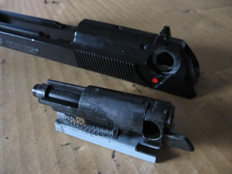
Slide Dissasembly[/u][/color]
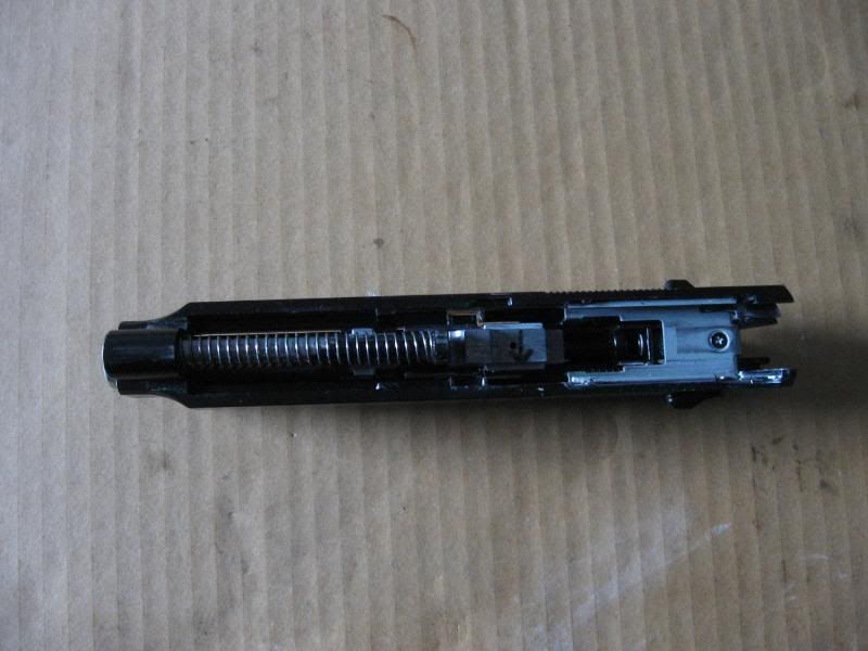
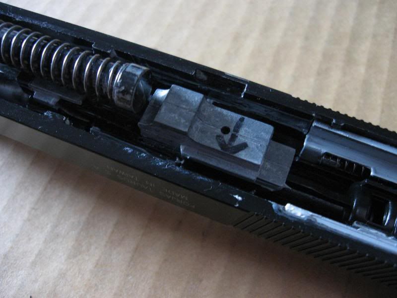
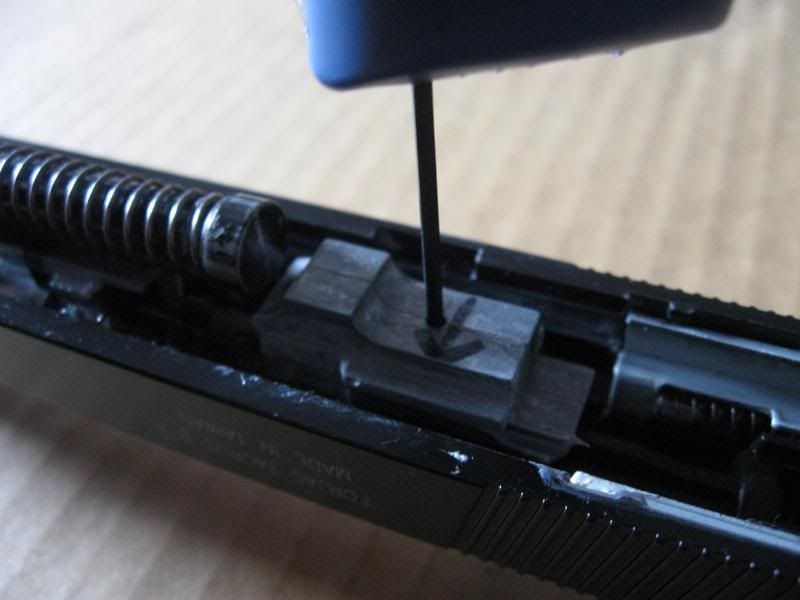
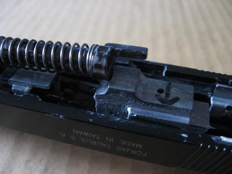
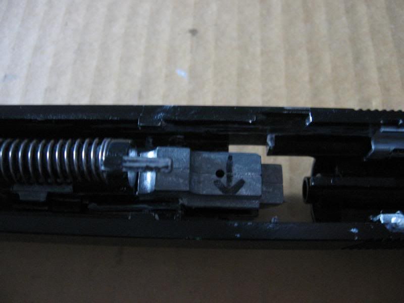
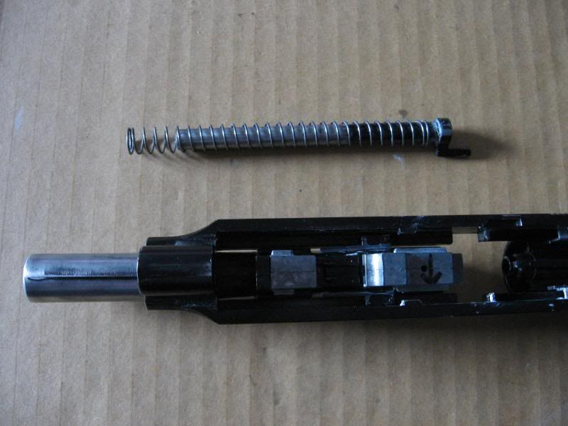
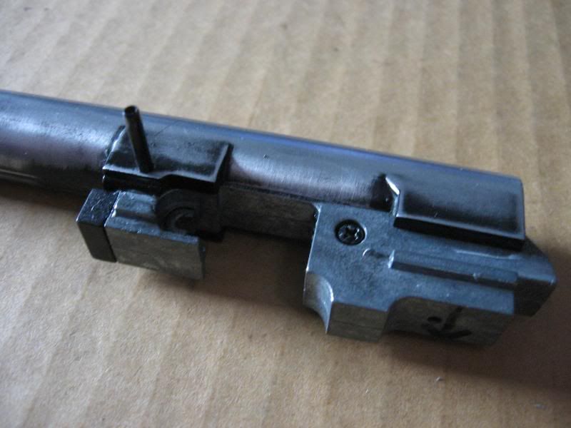
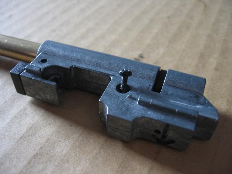
Here is the hop up unit. Adjustment is done by turning the allen head grub screw inside that hole. I drew the arrow on myself to remind myself that clockwise is UP, counter clockwise is DOWN.
Step 1: Remove recoil spring and guide rod.
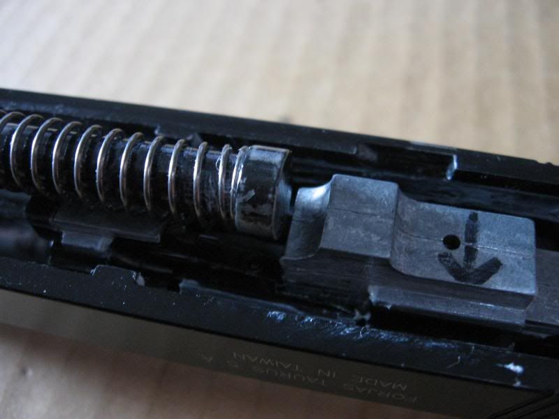
A. Pull back on the recoil spring guide rod.
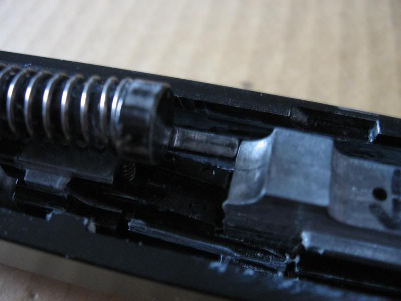
B. Rotate it so that the tab ends up over the hop up unit.
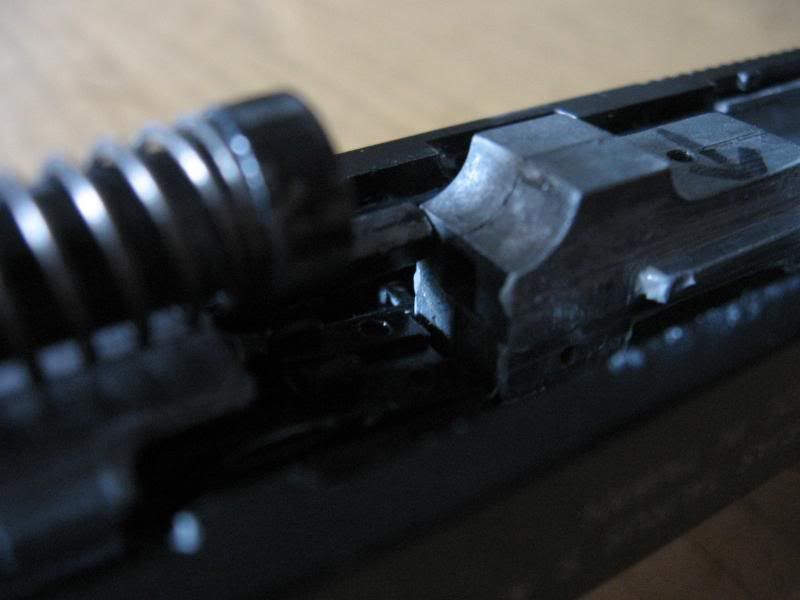
C. Pull back on the recoil guide rod and the hop up unit so that it disengages from the loading nozzle.
D. Remove the recoil guide rod and spring. Tilt the hop up unit out of the way and it will slide out.
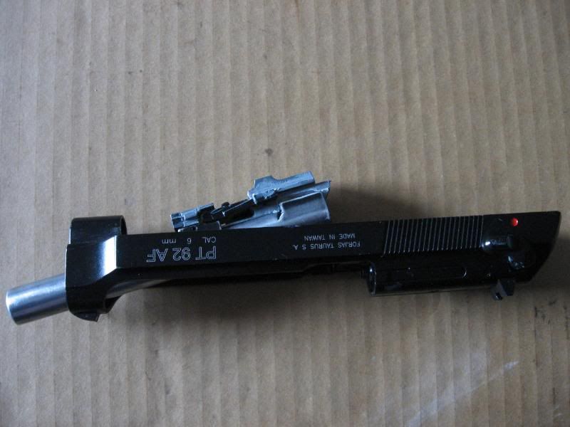
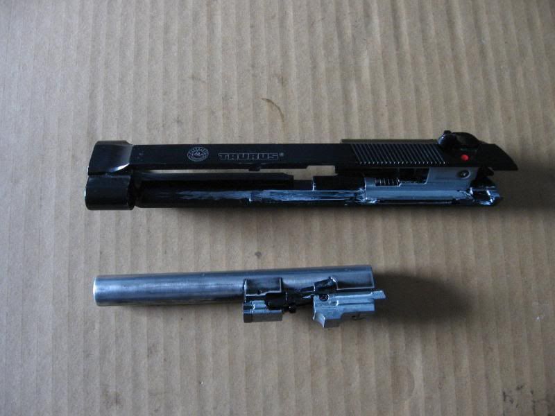
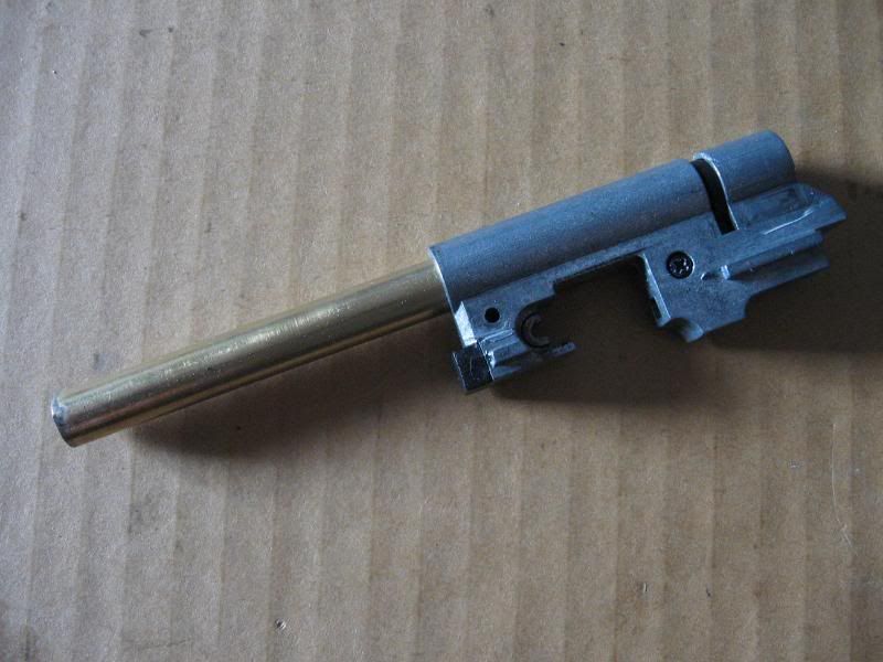
Step 2: Remove outer barrel and hop up unit from slide.
A. Simply tilt the outer barrel and hop up unit down from the slide, and pull it out.
Hop up dissasembly
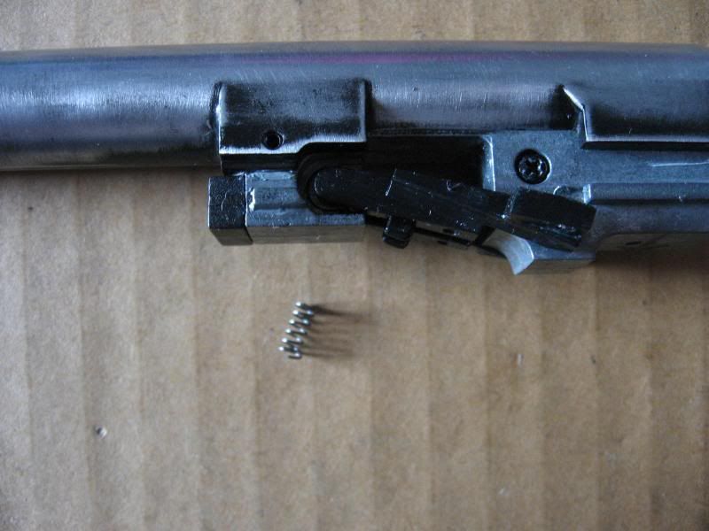
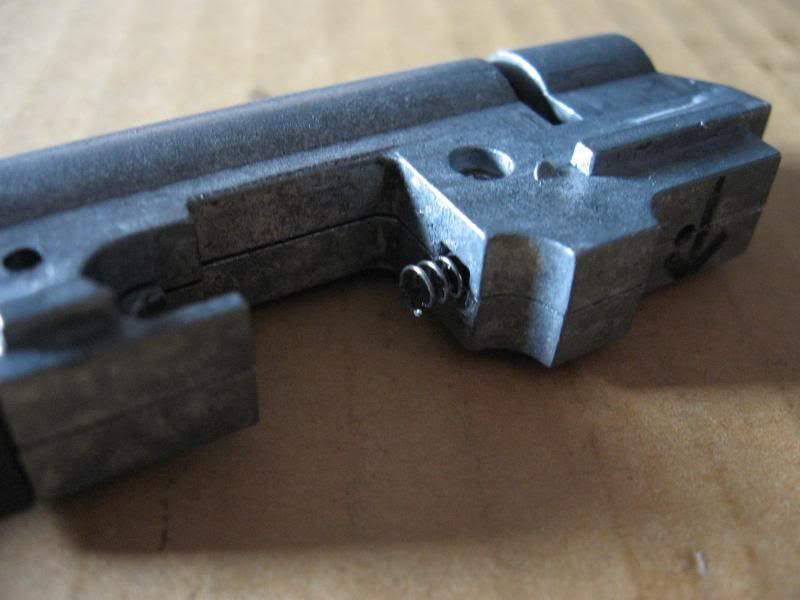
Spring warning! There is a small spring under the black plastic arm that can fly out during removal.
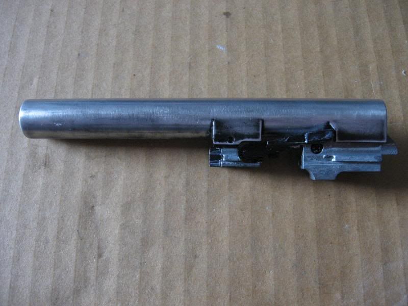
Here is the outer barrel and hop up unit. If you look closely between the black plastic piece on the bottom and the hop up unit there is a small spring. The plastic arm must be removed, and that small spring can easily go flying.
Step 1: Remove plastic arm.
A. Carefully use a pair of tweezers to pull the small spring out from between the black plastic arm and the hop up unit. I don't have a picture of this because it is impossible to do one handed.
Here is the spring removed, showing the size of it.
B. Pull plastic arm out of the hop up chamber. It is press fit.
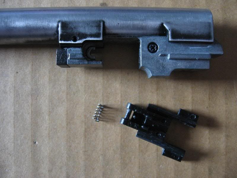
C. Drive out the pin that holds the hop up unit to the outer barrel.
D. Pull the hop up unit out of the outer barrel.
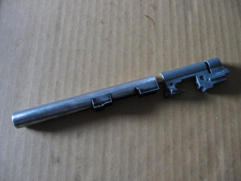
Here is the hop up unit and inner barrel.
E. Remove the phillips head screw.
F. Remove recoil guide rod tension spring. It may or may not have already fallen out. Mine tends to stick in the hop up unit. It is not held in by anything.
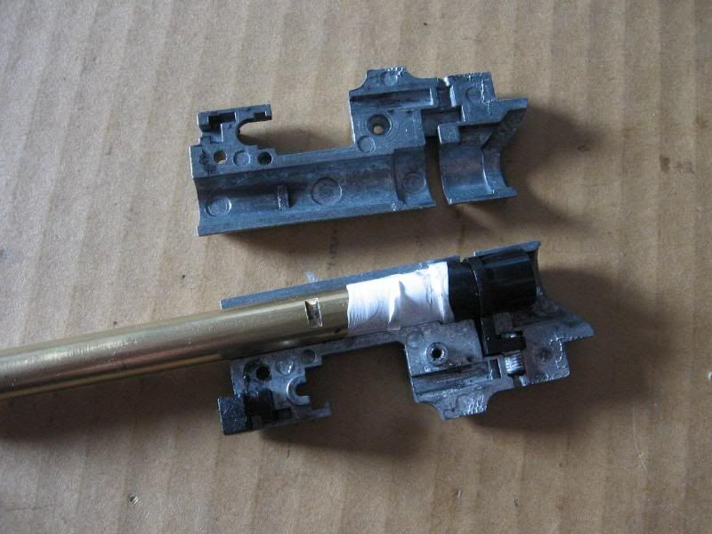
G. Seperate hop up unit shell.
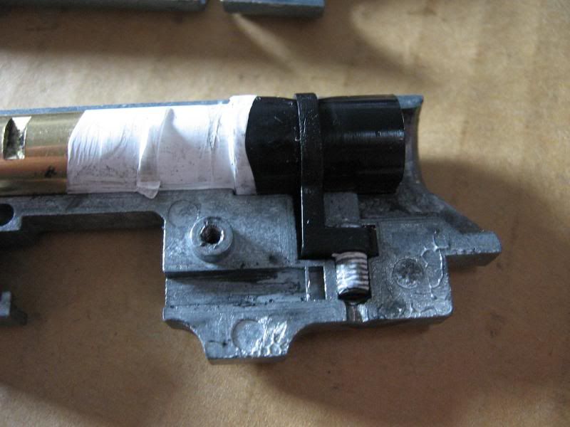
You will notice the teflon tape around the bucking and barrel. This is a modifcation I did and is not a factory part. I use silicone glue and telfon tape to make sure no air leaks past the bucking. I also added teflon tape around the hop up grub screw to stop it from backing off.
The hop up is simple to dissasemble, and because I sealed it I did not want to take it apart. From here simply pull the bucking off the barrel, then remove the plastic hop up arm. There is no nub for the bucking, so don't worry about losing it.
Blow back dissasembly
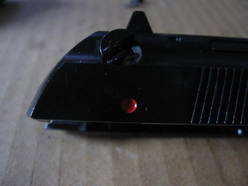
Step 1: Remove safety levers.
A. Remove grub screw from right side lever.
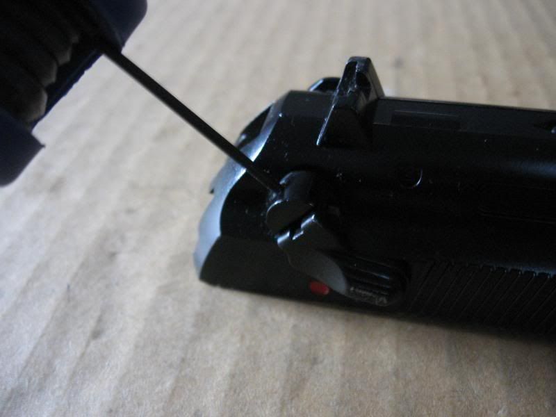
B. Remove arm and remove grub screw completely.
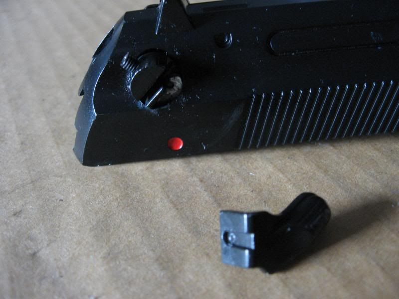
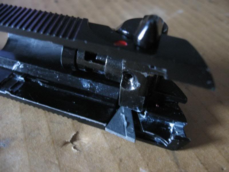
This next step is problematic. Sometimes the safety arm does not want to come out. Keep rotating and wiggling and it should eventually slide out. Also, the rear of the loading nozzle extends into the lever area. Pull the loading nozzle forward a little to clear the levers.
C. Push the left side saftey lever out of the slide.
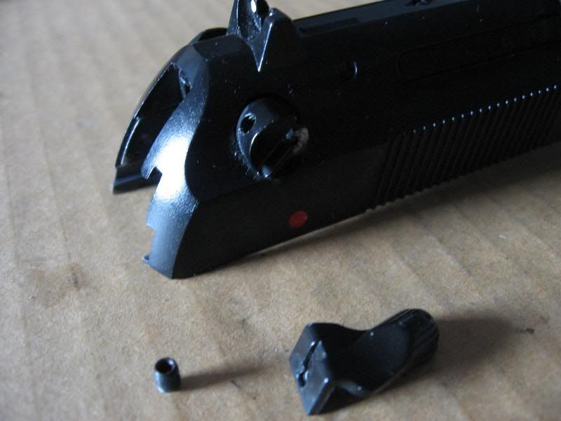
Spring warning! There is a small spring and pin housed in the left lever. When pushing the lever out be careful that this pin does not go flying
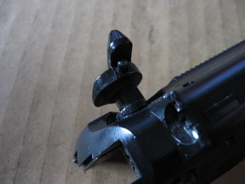
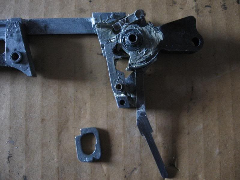
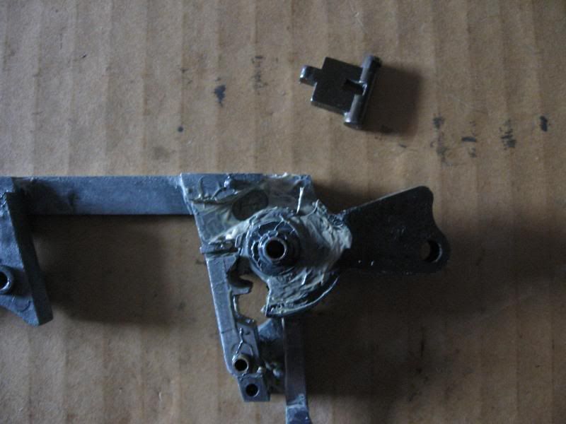
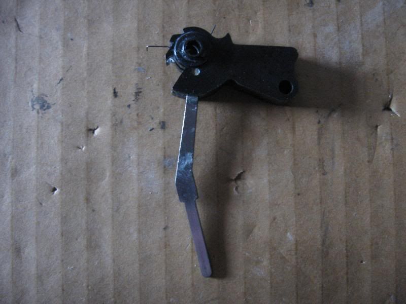
The silver hook is the safety arm. Make sure to study how it fits in before removing it. If it is not placed back in the safety will not work.
Here is the safety arm from the inside view.
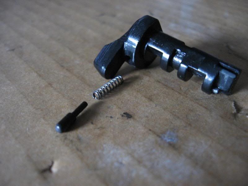
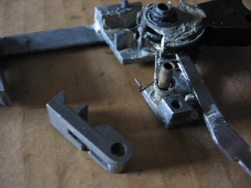
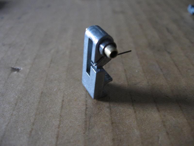
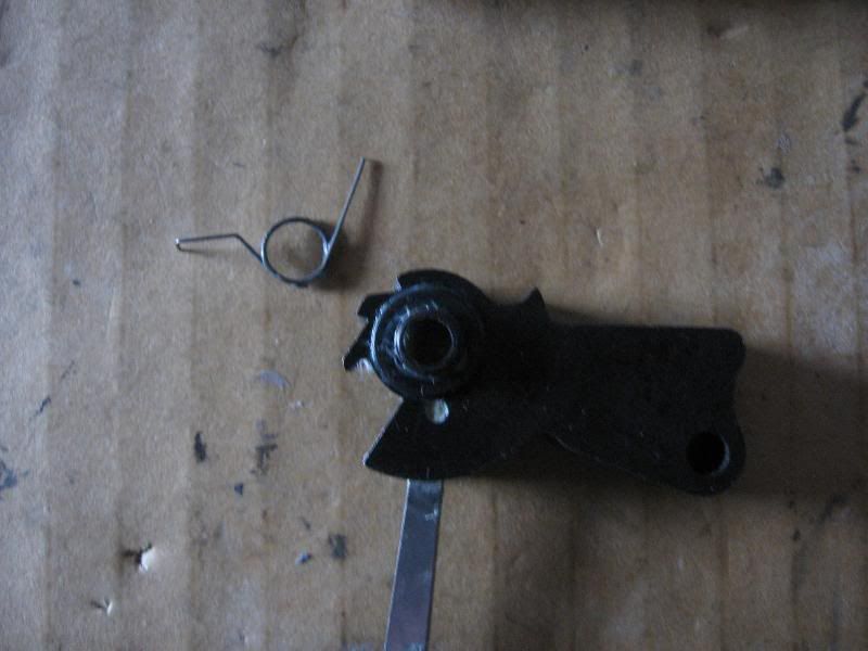
This is the pin and spring.
Pin and spring removed from arm.
D. Remove screw holding the blow back unit plate in.
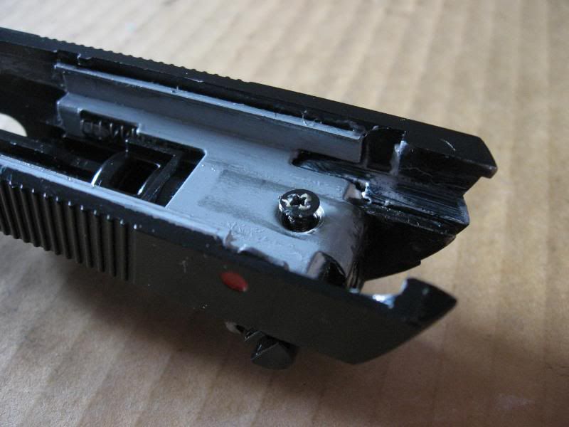
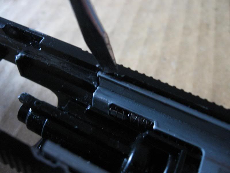
E. Remove blow back unit plate from slide. Using a screw driver pry the plate past the two protrusions on the slide.
Spring warning! The blow back unit has two springs that are held in by tension. Be careful while removing plate and unit.
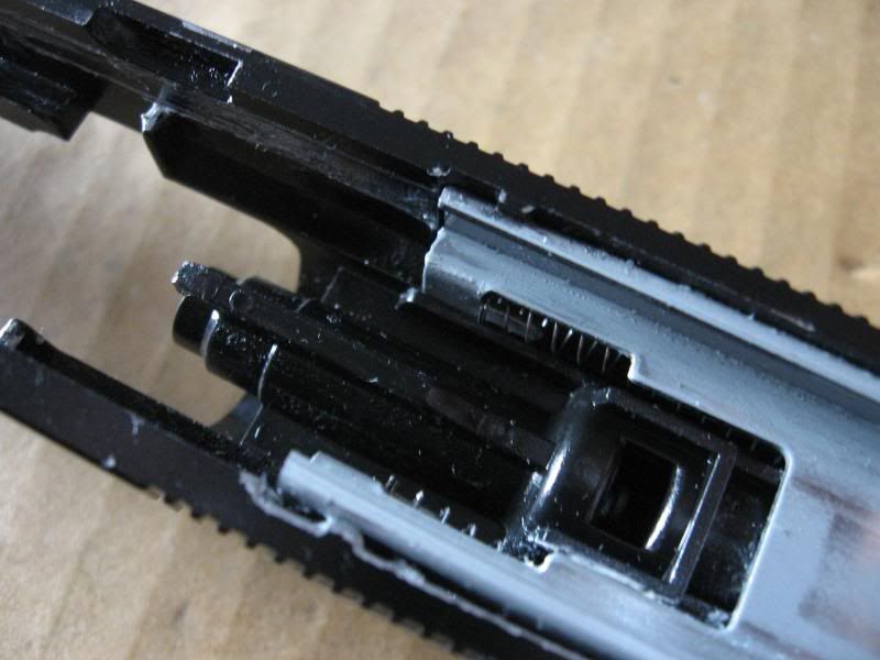
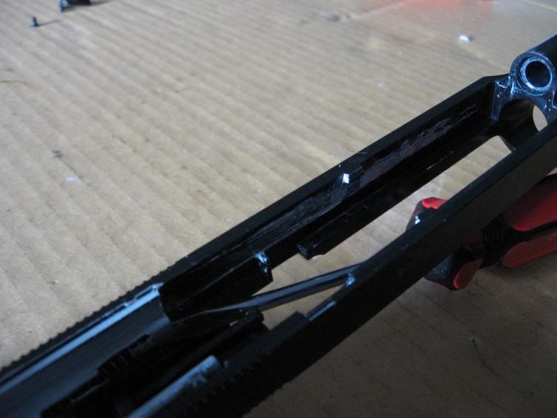
F. Remove blow back unit from slide.
G. Dissasemble blow back unit.
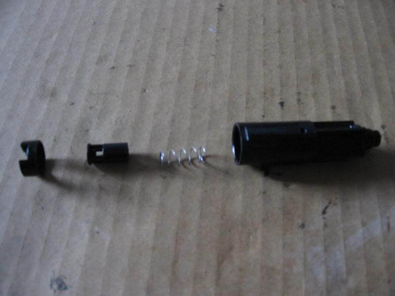
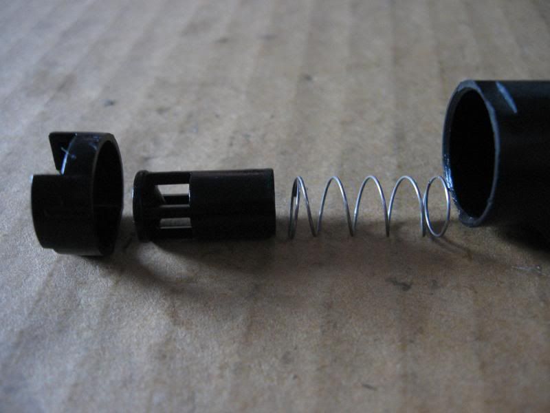
A. Remove the springs, pull the loading nozzle off of the power cup.
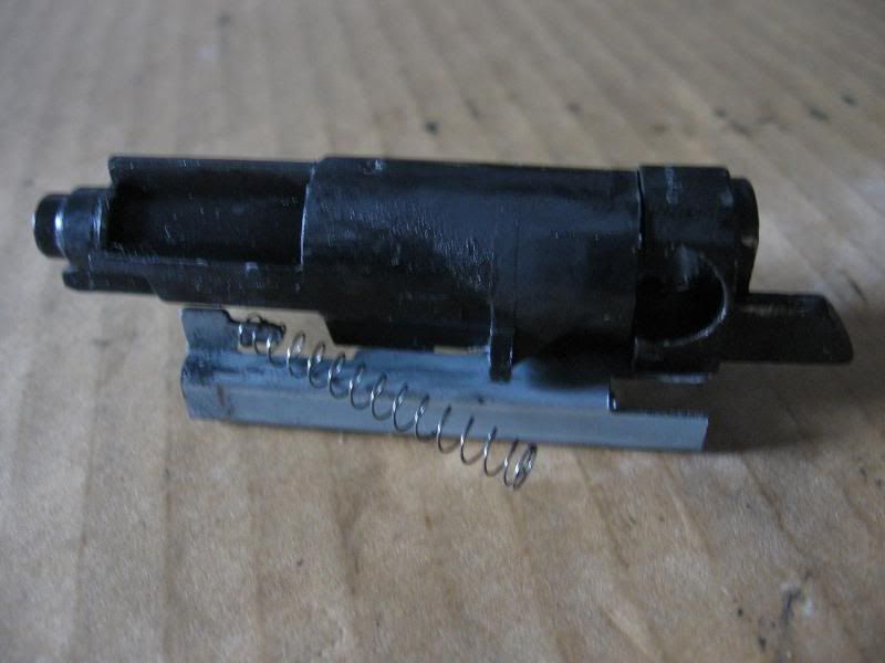
Blow back unit dissasembled.
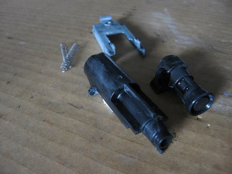
You shouldn't have to dissasemble the loading nozzle, but if for some reason you do, follow along.
Spring warning! Inside the nozzle is a spring. It isn't very strong, but it could still come out. When Removing the tiny screw put your finger over the back of the nozzle to hold the spring in.
A. Remove tiny phillips screw
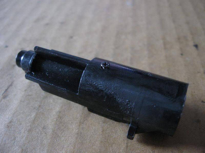
Nozzle fully dissasembled.
Make sure the pieces go back in correctly. If not the valve will not fit.
The slide is now fully dissasembled.
Frame dissasembly
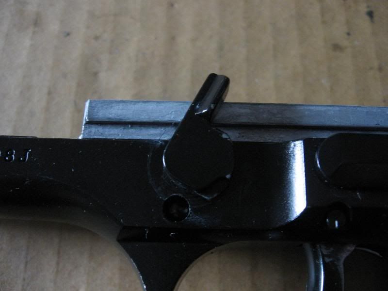
Step 1: Remove takedown lever.
A. Push the small oval button in, and rotate the takedown lever the opposite way as removal. It might hang up on the slide rails, if it does pull it out a little.
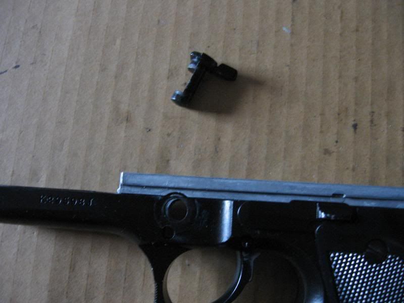
B. Remove the oval button and takedown lever. Take note of which way the oval button and spring go into the frame.
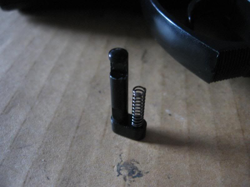
Note spring cup and hole for button to pass through.
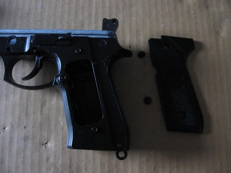
Step 2: Remove grips
Spring warning! ALWAYS be careful when removing the RIGHT grip from any M9 as there is a spring that is held in by the grip itself. Also watch for the slide catch spring.
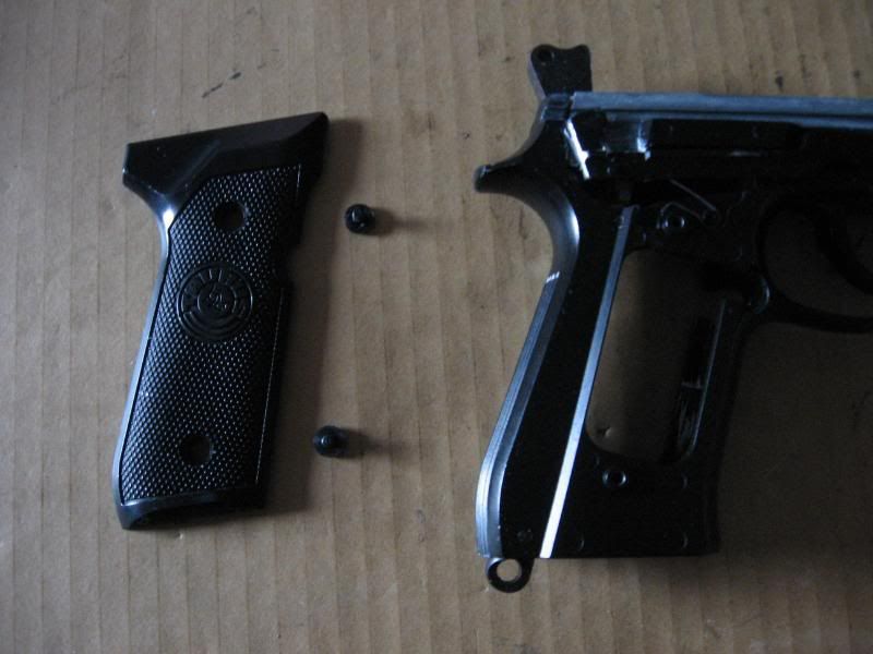
A. Remove the LEFT grip by removing the two flathead screws. No springs will fly out of the LEFT grip.
B. Remove the mag catch. For you left handers the mag catch can be flipped for ambedextrous use. For you right handers make sure you put it back the way you removed it.
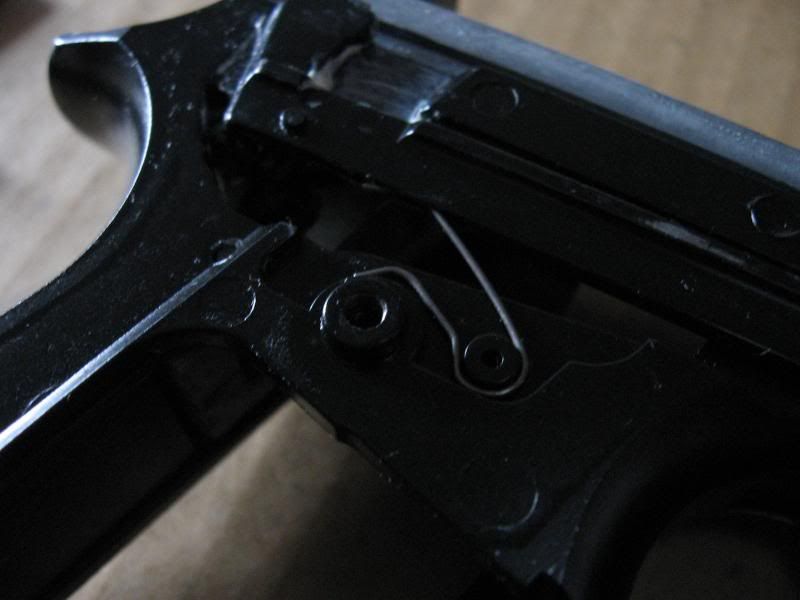
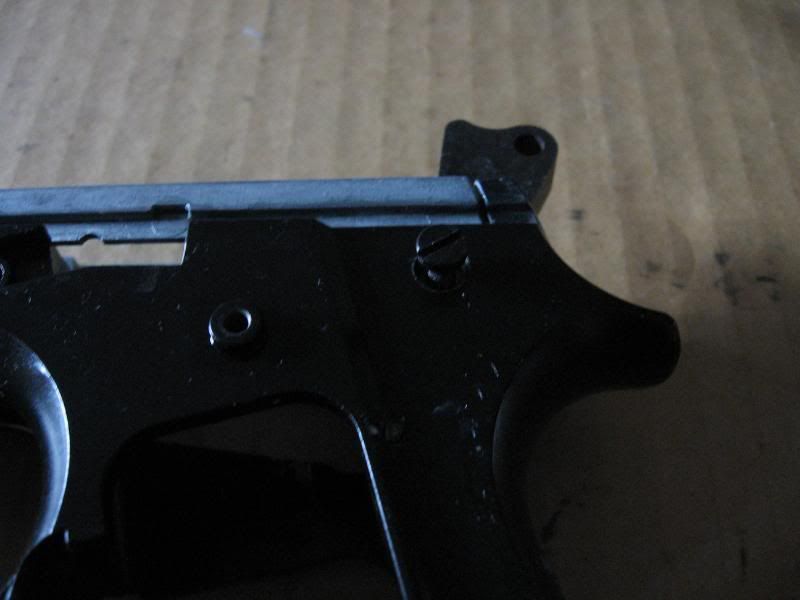
C. Spring warning! Remove the slide catch. The spring is wrapped around the post and will not fly out, but pull the catch out slowly to prevent it from going anywhere.
Note the position of the spring
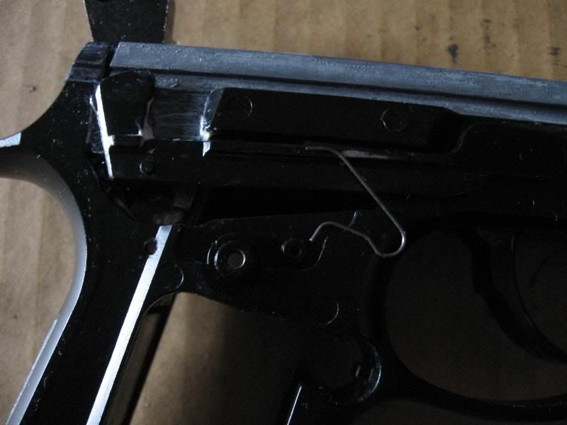
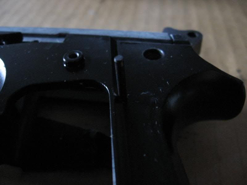
D. Spring warning! Before removing the RIGHT grip, pull the trigger to decock the external hammer. While Keeping pressure on the RIGHT grip remove the screws but DO NOT remove the grip. Once the screws are out hold the external trigger bar down and then SLOWLY remove the grip. There is a spring under the RIGHT[/b] grip that can easily go flying because it's held down by the grip itself.
The spring you need to be careful with. Notice how nothing really holds it in.
E. Remove the above spring. Carefully pull the top of the spring out of the groove in the external trigger bar.
Step 3: If the hammer is still cocked, push up on the external trigger bar and pull the trigger to decock it. Then remove the external trigger bar. Nothing holds it in so simply pull it out.
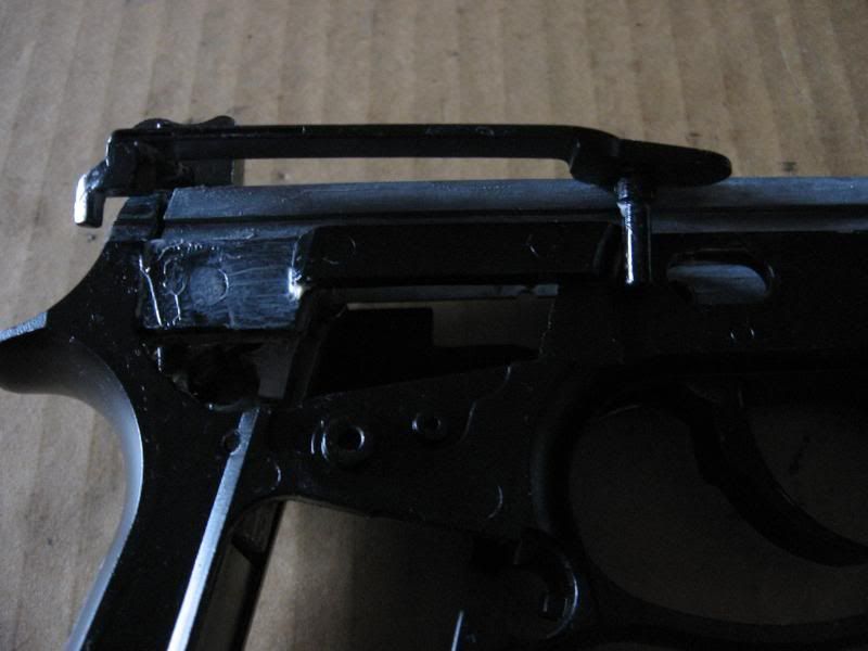
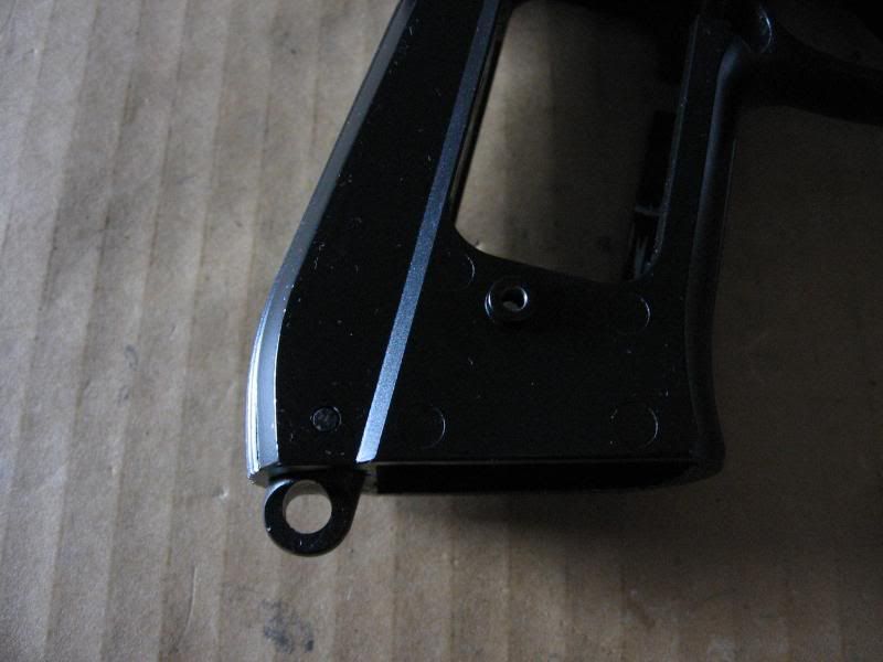
If your KJW M9 does not have a lanyard loop it may use a plastic housing instead to hold the spring. Either way dissasembly is exactly the same.
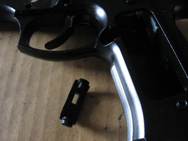
Spring warning! The hammer spring can be problematic. It is faily powerful and can easily send the stopper flying. Be careful during this step.
Step 4: Remove hammer spring.
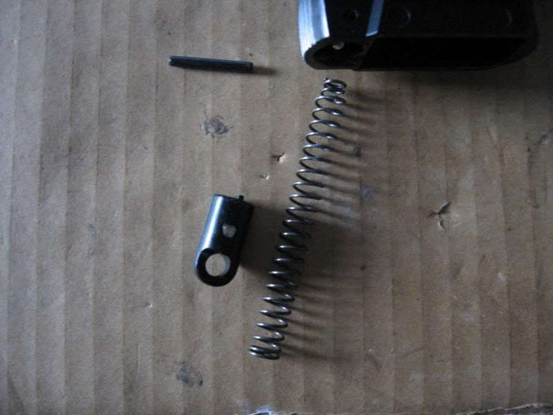
A. Press out the pin at the bottom of the handle. REMEMBER!! That pin is the only thing holding the spring and stopper in, make sure to hold the stopper while pressing out the pin.
Here is the pin, spring, and stopper removed. Make sure the hammer spring goes back in with the small diameter side first, if it doesn't the hammer won't work. Also, make sure the external hammer bar goes into the center of the spring. If it's just crammed in there the hammer will bind.
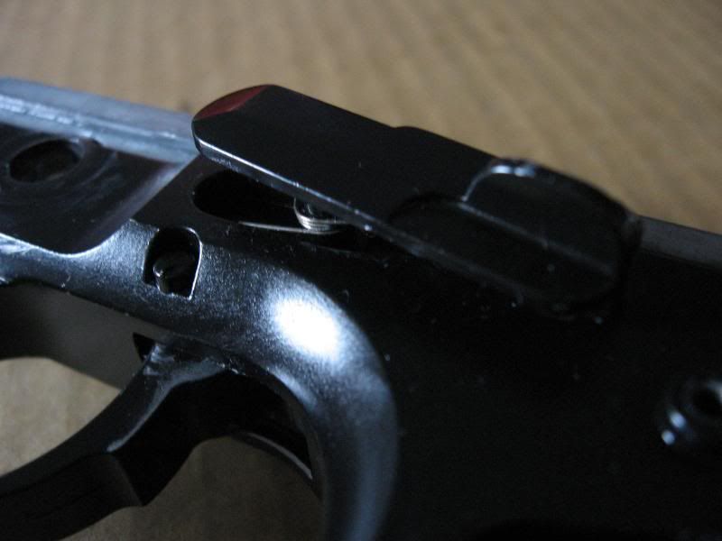
Step 5: Remove trigger mechanism from frame.
A. Remove this flathead screw from left side of frame.
B. Press out the pin directly below the flathead screw.
Spring warning! There is a small spring on the LEFT side of the mechanism that can easily snag and pop out. It won't fly out right away, so just watch out for it.
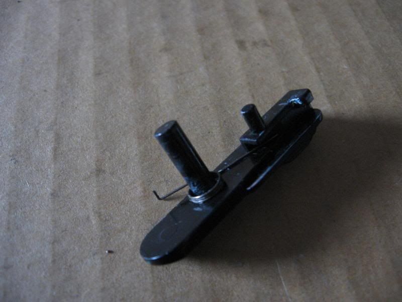
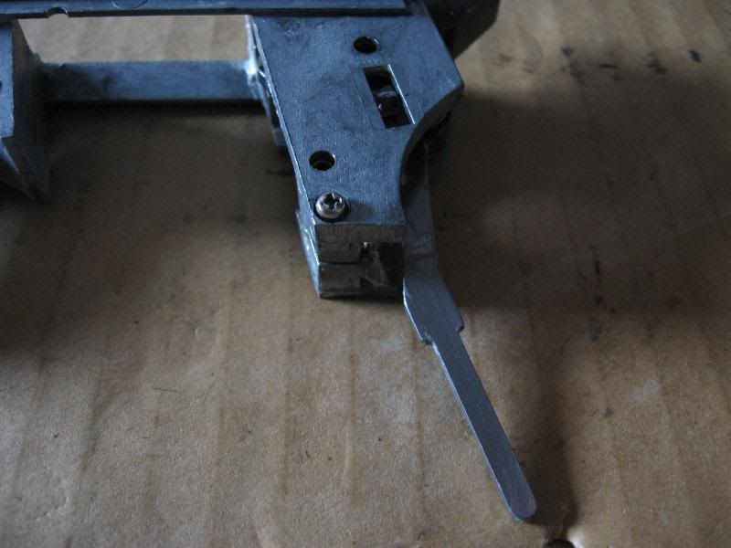
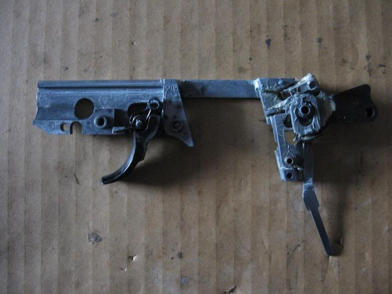
C. Pull the mechanism out of the frame. Note the long chrome bar coming from the external hammer. That bar needs to be centered in the hammer spring.
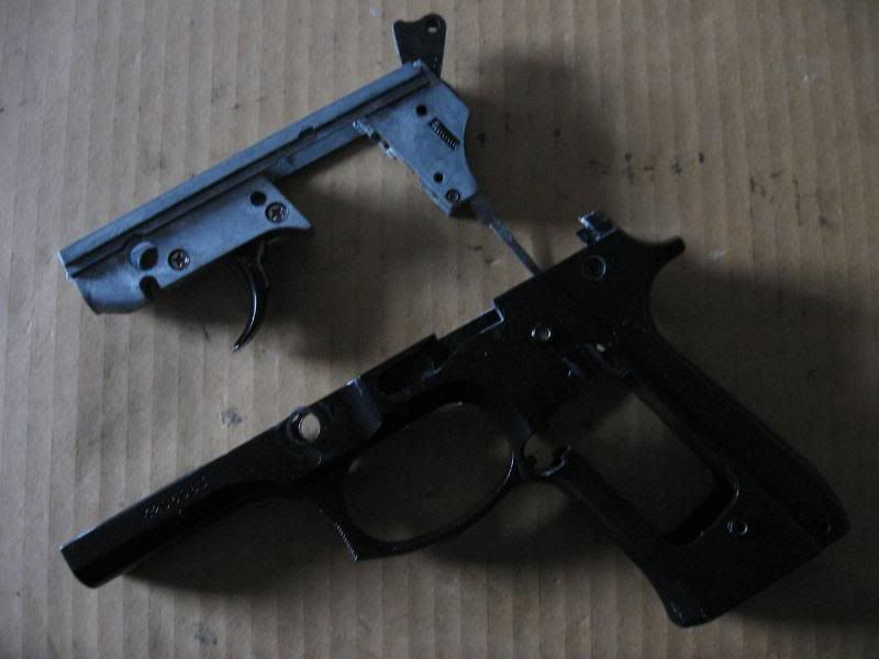
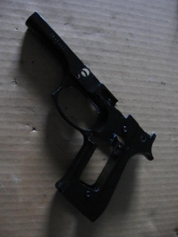
The frame is now fully dissasembled.
Trigger mechanism dissasembly
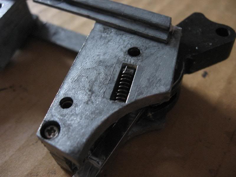
Spring warning! If you are going to take the trigger mechanism apart every step will have springs popping off of their retention posts. When the case is opened the internal hammer will pop out right away. If you are not mechanically inclined I recommend you leave this together. It can be cleaned and lubed without being taken apart. If your trigger spring is broken remove the front screws and follow the last step. DO NOT remove the little screw if you can't put it back together!
Step 1: Remove the small spring on the left side of the case.
Step 2: Seperate the case. Be aware that spreading the case WILL pop the springs, hammer, and mechanism out of place!
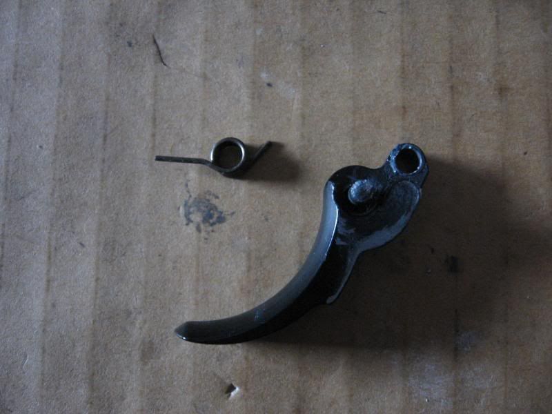
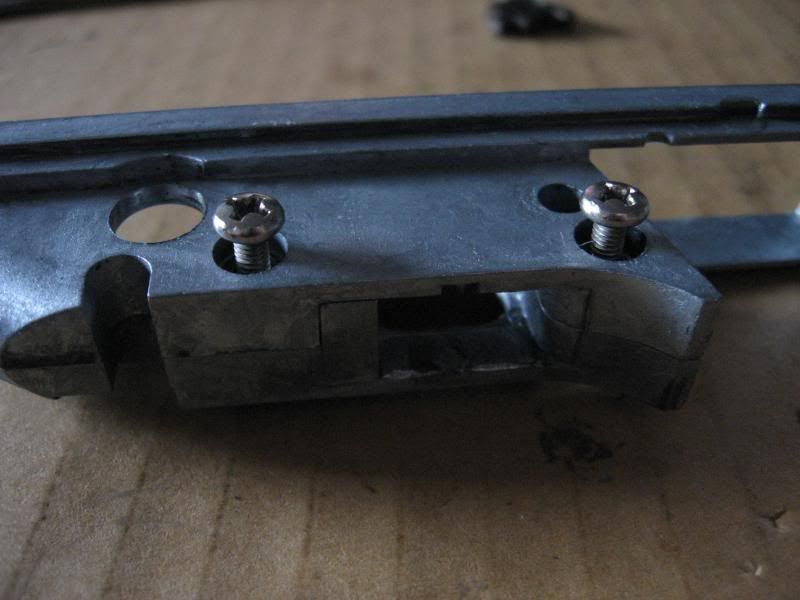
A. Remove the two large philips head screws. Then pull out the trigger and trigger spring. The trigger spring shouldn't go flying as it isn't under much tension.
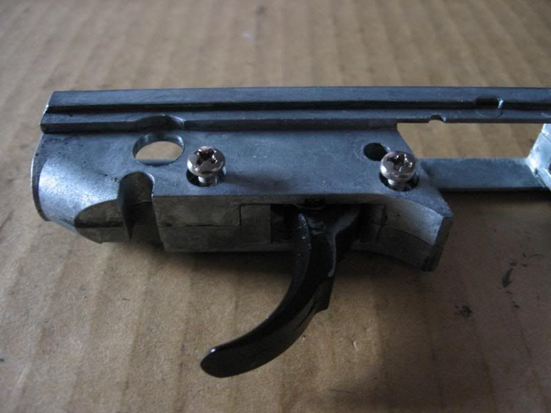
B. Remove the one small philips head screw at the bottom of the case.
C. Open the case. I would recommend trying to hold down the internal hammer with a small screw driver if possible. Springs should not fly out, but the internal hammer might.
Trigger and trigger spring.
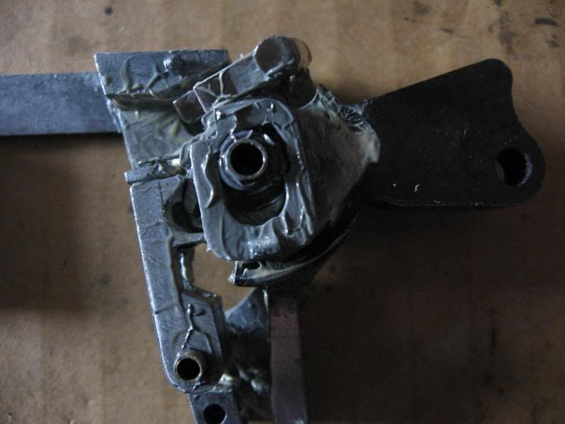
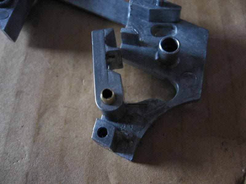
Step 3: Remove and clean the mechanism. I added the grease to my M9, it is not factory lubrication.
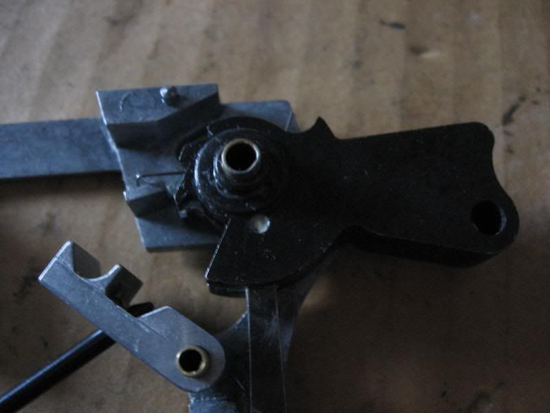
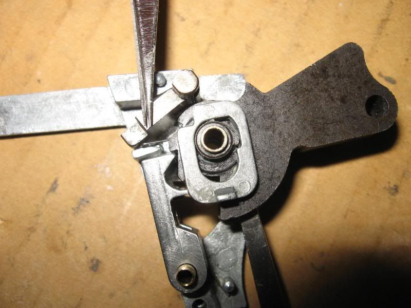
A. Remove the square shaped part.
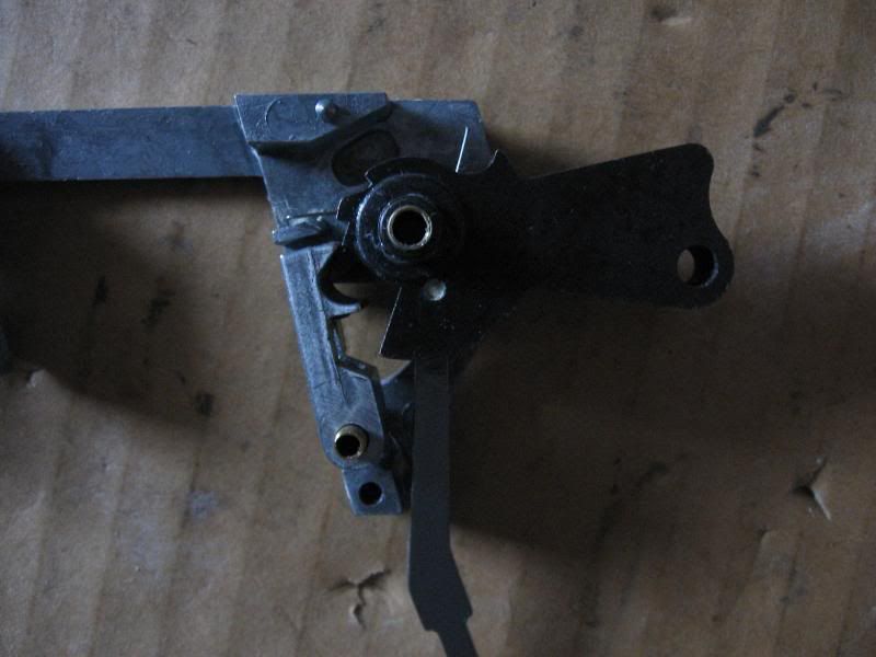
B. Remove the internal hammer.
C. Remove sear, spring, and post.
The sear, post, and spring shown cleaned and assembled. Note that the bent end of the spring wraps around the cutout on the sear.
D. Remove the external hammer, spring, and post.
Here is the spring that goes inside the external hammer.
Trigger mechanism reassembly
Step 1: Check clearances and shim or file away things that are out of spec. Lube any and all contact points along the way.
Step 2: Install the sear, spring, and post.
A. Install the post first, then slip the spring and sear over it.
B. Using the needlenose pliers slide the spring over the retention post.
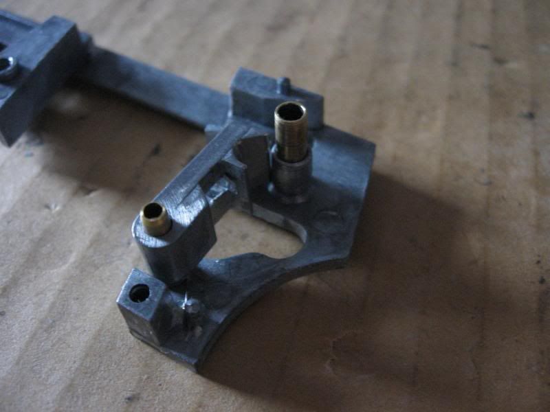
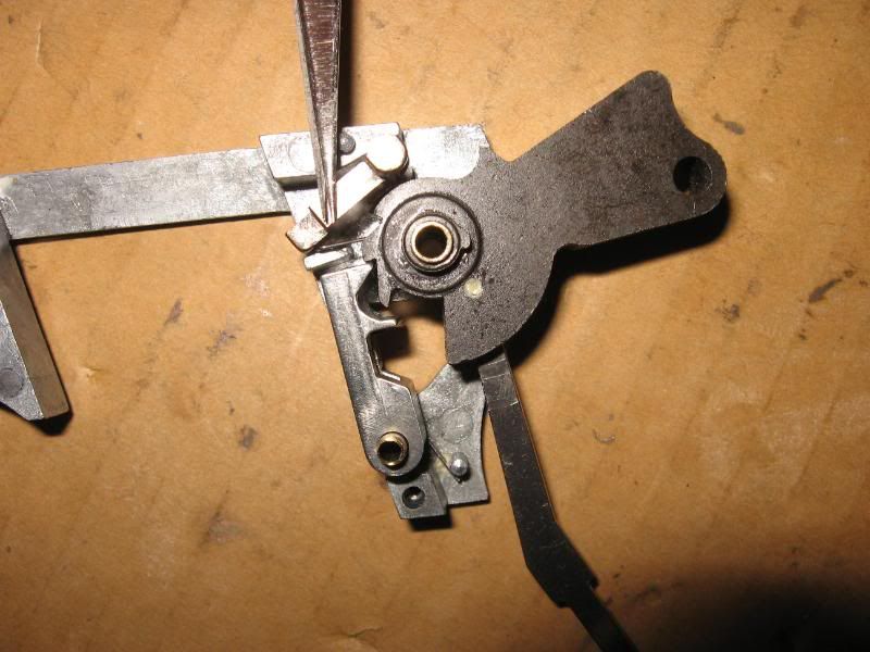
Step 3: Install external hammer, spring, and post. Install the post into the case, then slide the spring and external hammer over it. Make sure the "L" shaped part of the spring is held by the retention post at about 10 O'clock, and the straight part of the spring is pointing to about 2 O'clock. Note that I'm holding the sear with a screw driver, it will want to spring forward.
Here is how the sear and hammer should fit together when assembled. Nothing here should want to fly out.
Step 4: Install internal hammer.
This is the hardest part of assembling the trigger mechanism. The hammer will always want to fly out. Make sure the hammer goes in correctly with the post with the square carved out is pointing up. The straight end of the external hammer spring needs to go into the square hole of the internal hammer. Once the spring is in the hole slide the internal hammer into the grooves in the case.
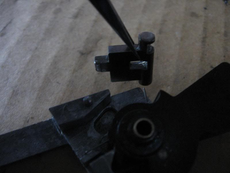
Now for some high detail flash pictures. Just in case you couldn't make out what I was doing above. Note that I'm holding the internal hammer with tweezers, it will always want to fly out.
Step 5: Install square block. Make sure to align it properly with the cut out and the spring block.
Step 6: Reinstall the other half of the case. Make sure the two large philips head screws are only threaded in, but not tightned. Don't try to wedge the trigger in yet, that's next.
Step 7: Install the trigger.
A. With the screws only partially installed slide the trigger and trigger spring in from the bottom.
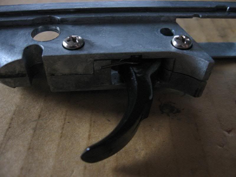
B. Spread the case a little and using a small flathead screwdriver push the trigger spring between the gap and into the case.
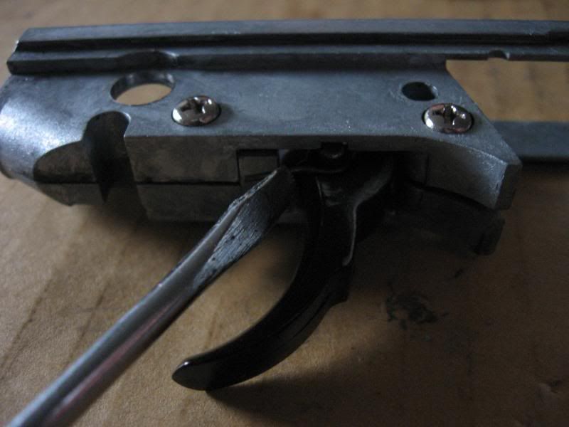
C. Tighten the screws.
D. Reassemble the entire M9 again. Simply reverse the dissasembly process to put everything back together.
Edit 1: Fixed repeating issue. Thanks Ike.
This is version 1.0. Any errors or problems will be fixed in future updates. If you see any problems point them out for me and it will make for a better guide.
This guide may not be copied and posted on other sites. If you wish to share the information please post a link to this thread.
Welcome to the complete KJW M9 GBB dissasembly Guide. Before you begin taking your KJW M9 apart please read the entire guide. There are springs in certain areas that can fly out when a part is removed. To help avoid this and any other confusion please read the whole guide before trying dissasemble anything.
I made this guide to help others fix their KJW M9 GBB pistols. By following this guide you are dissasembling your M9 at your own risk. If you have trouble shoot me a PM and I will be glad to help. But I will not pay for any replacement parts or pieces.
With all that out of the way, lets begin.
Tools needed for complete dissasembly:
- 1 set small needle nose pliers
- 1 pair of tweezers
- 1.5mm allen key
- 1 tiny flathead
- 1 small flathead
- 1 large flathead
- 1 tiny philips head
- 1 small philips
- 1 large philiphs head
If you are cleaning or lubing you will also need grease. What kind you use is up to you, but I use white lithium.
Now that you have the tools, you will need the KJW M9 GBB. My specific example is a KJW Taurus branded M9.
Basic teardown[/b][/color]
Step 1: Clear the gun. Make sure there are no BB's in the chamber and that the magazine is removed.
Step 2: Remove the slide.
A. Cock the hammer back.
B. Press the small oval button on the right side of the frame near the trigger guard.
C. Pull down on the dissasembly lever.
D. Push the slide forward and remove it from the frame.
Slide Dissasembly[/u][/color]
Here is the hop up unit. Adjustment is done by turning the allen head grub screw inside that hole. I drew the arrow on myself to remind myself that clockwise is UP, counter clockwise is DOWN.
Step 1: Remove recoil spring and guide rod.
A. Pull back on the recoil spring guide rod.
B. Rotate it so that the tab ends up over the hop up unit.
C. Pull back on the recoil guide rod and the hop up unit so that it disengages from the loading nozzle.
D. Remove the recoil guide rod and spring. Tilt the hop up unit out of the way and it will slide out.
Step 2: Remove outer barrel and hop up unit from slide.
A. Simply tilt the outer barrel and hop up unit down from the slide, and pull it out.
Hop up dissasembly
Spring warning! There is a small spring under the black plastic arm that can fly out during removal.
Here is the outer barrel and hop up unit. If you look closely between the black plastic piece on the bottom and the hop up unit there is a small spring. The plastic arm must be removed, and that small spring can easily go flying.
Step 1: Remove plastic arm.
A. Carefully use a pair of tweezers to pull the small spring out from between the black plastic arm and the hop up unit. I don't have a picture of this because it is impossible to do one handed.
Here is the spring removed, showing the size of it.
B. Pull plastic arm out of the hop up chamber. It is press fit.
C. Drive out the pin that holds the hop up unit to the outer barrel.
D. Pull the hop up unit out of the outer barrel.
Here is the hop up unit and inner barrel.
E. Remove the phillips head screw.
F. Remove recoil guide rod tension spring. It may or may not have already fallen out. Mine tends to stick in the hop up unit. It is not held in by anything.
G. Seperate hop up unit shell.
You will notice the teflon tape around the bucking and barrel. This is a modifcation I did and is not a factory part. I use silicone glue and telfon tape to make sure no air leaks past the bucking. I also added teflon tape around the hop up grub screw to stop it from backing off.
The hop up is simple to dissasemble, and because I sealed it I did not want to take it apart. From here simply pull the bucking off the barrel, then remove the plastic hop up arm. There is no nub for the bucking, so don't worry about losing it.
Blow back dissasembly
Step 1: Remove safety levers.
A. Remove grub screw from right side lever.
B. Remove arm and remove grub screw completely.
This next step is problematic. Sometimes the safety arm does not want to come out. Keep rotating and wiggling and it should eventually slide out. Also, the rear of the loading nozzle extends into the lever area. Pull the loading nozzle forward a little to clear the levers.
C. Push the left side saftey lever out of the slide.
Spring warning! There is a small spring and pin housed in the left lever. When pushing the lever out be careful that this pin does not go flying
The silver hook is the safety arm. Make sure to study how it fits in before removing it. If it is not placed back in the safety will not work.
Here is the safety arm from the inside view.
This is the pin and spring.
Pin and spring removed from arm.
D. Remove screw holding the blow back unit plate in.
E. Remove blow back unit plate from slide. Using a screw driver pry the plate past the two protrusions on the slide.
Spring warning! The blow back unit has two springs that are held in by tension. Be careful while removing plate and unit.
F. Remove blow back unit from slide.
G. Dissasemble blow back unit.
A. Remove the springs, pull the loading nozzle off of the power cup.
Blow back unit dissasembled.
You shouldn't have to dissasemble the loading nozzle, but if for some reason you do, follow along.
Spring warning! Inside the nozzle is a spring. It isn't very strong, but it could still come out. When Removing the tiny screw put your finger over the back of the nozzle to hold the spring in.
A. Remove tiny phillips screw
Nozzle fully dissasembled.
Make sure the pieces go back in correctly. If not the valve will not fit.
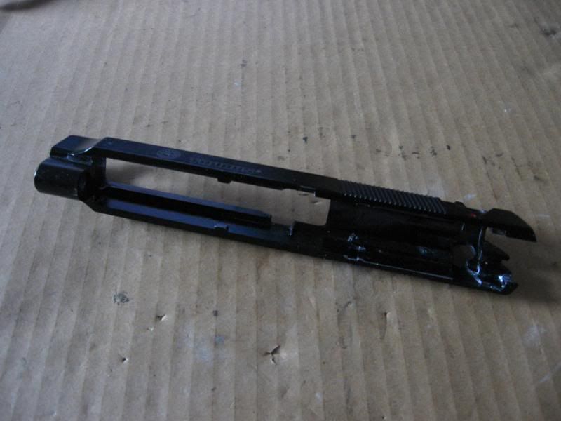
The slide is now fully dissasembled.
Frame dissasembly
Step 1: Remove takedown lever.
A. Push the small oval button in, and rotate the takedown lever the opposite way as removal. It might hang up on the slide rails, if it does pull it out a little.
B. Remove the oval button and takedown lever. Take note of which way the oval button and spring go into the frame.
Note spring cup and hole for button to pass through.
Step 2: Remove grips
Spring warning! ALWAYS be careful when removing the RIGHT grip from any M9 as there is a spring that is held in by the grip itself. Also watch for the slide catch spring.
A. Remove the LEFT grip by removing the two flathead screws. No springs will fly out of the LEFT grip.
B. Remove the mag catch. For you left handers the mag catch can be flipped for ambedextrous use. For you right handers make sure you put it back the way you removed it.
C. Spring warning! Remove the slide catch. The spring is wrapped around the post and will not fly out, but pull the catch out slowly to prevent it from going anywhere.
Note the position of the spring
D. Spring warning! Before removing the RIGHT grip, pull the trigger to decock the external hammer. While Keeping pressure on the RIGHT grip remove the screws but DO NOT remove the grip. Once the screws are out hold the external trigger bar down and then SLOWLY remove the grip. There is a spring under the RIGHT[/b] grip that can easily go flying because it's held down by the grip itself.
The spring you need to be careful with. Notice how nothing really holds it in.
E. Remove the above spring. Carefully pull the top of the spring out of the groove in the external trigger bar.
Step 3: If the hammer is still cocked, push up on the external trigger bar and pull the trigger to decock it. Then remove the external trigger bar. Nothing holds it in so simply pull it out.
If your KJW M9 does not have a lanyard loop it may use a plastic housing instead to hold the spring. Either way dissasembly is exactly the same.
Spring warning! The hammer spring can be problematic. It is faily powerful and can easily send the stopper flying. Be careful during this step.
Step 4: Remove hammer spring.
A. Press out the pin at the bottom of the handle. REMEMBER!! That pin is the only thing holding the spring and stopper in, make sure to hold the stopper while pressing out the pin.
Here is the pin, spring, and stopper removed. Make sure the hammer spring goes back in with the small diameter side first, if it doesn't the hammer won't work. Also, make sure the external hammer bar goes into the center of the spring. If it's just crammed in there the hammer will bind.
Step 5: Remove trigger mechanism from frame.
A. Remove this flathead screw from left side of frame.
B. Press out the pin directly below the flathead screw.
Spring warning! There is a small spring on the LEFT side of the mechanism that can easily snag and pop out. It won't fly out right away, so just watch out for it.
C. Pull the mechanism out of the frame. Note the long chrome bar coming from the external hammer. That bar needs to be centered in the hammer spring.
The frame is now fully dissasembled.
Trigger mechanism dissasembly
Spring warning! If you are going to take the trigger mechanism apart every step will have springs popping off of their retention posts. When the case is opened the internal hammer will pop out right away. If you are not mechanically inclined I recommend you leave this together. It can be cleaned and lubed without being taken apart. If your trigger spring is broken remove the front screws and follow the last step. DO NOT remove the little screw if you can't put it back together!
Step 1: Remove the small spring on the left side of the case.
Step 2: Seperate the case. Be aware that spreading the case WILL pop the springs, hammer, and mechanism out of place!
A. Remove the two large philips head screws. Then pull out the trigger and trigger spring. The trigger spring shouldn't go flying as it isn't under much tension.
B. Remove the one small philips head screw at the bottom of the case.
C. Open the case. I would recommend trying to hold down the internal hammer with a small screw driver if possible. Springs should not fly out, but the internal hammer might.
Trigger and trigger spring.
Step 3: Remove and clean the mechanism. I added the grease to my M9, it is not factory lubrication.
A. Remove the square shaped part.
B. Remove the internal hammer.
C. Remove sear, spring, and post.
The sear, post, and spring shown cleaned and assembled. Note that the bent end of the spring wraps around the cutout on the sear.
D. Remove the external hammer, spring, and post.
Here is the spring that goes inside the external hammer.
Trigger mechanism reassembly
Step 1: Check clearances and shim or file away things that are out of spec. Lube any and all contact points along the way.
Step 2: Install the sear, spring, and post.
A. Install the post first, then slip the spring and sear over it.
B. Using the needlenose pliers slide the spring over the retention post.
Step 3: Install external hammer, spring, and post. Install the post into the case, then slide the spring and external hammer over it. Make sure the "L" shaped part of the spring is held by the retention post at about 10 O'clock, and the straight part of the spring is pointing to about 2 O'clock. Note that I'm holding the sear with a screw driver, it will want to spring forward.
Here is how the sear and hammer should fit together when assembled. Nothing here should want to fly out.
Step 4: Install internal hammer.
This is the hardest part of assembling the trigger mechanism. The hammer will always want to fly out. Make sure the hammer goes in correctly with the post with the square carved out is pointing up. The straight end of the external hammer spring needs to go into the square hole of the internal hammer. Once the spring is in the hole slide the internal hammer into the grooves in the case.
Now for some high detail flash pictures. Just in case you couldn't make out what I was doing above. Note that I'm holding the internal hammer with tweezers, it will always want to fly out.
Step 5: Install square block. Make sure to align it properly with the cut out and the spring block.
Step 6: Reinstall the other half of the case. Make sure the two large philips head screws are only threaded in, but not tightned. Don't try to wedge the trigger in yet, that's next.
Step 7: Install the trigger.
A. With the screws only partially installed slide the trigger and trigger spring in from the bottom.
B. Spread the case a little and using a small flathead screwdriver push the trigger spring between the gap and into the case.
C. Tighten the screws.
D. Reassemble the entire M9 again. Simply reverse the dissasembly process to put everything back together.
Edit 1: Fixed repeating issue. Thanks Ike.